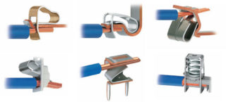
Electrical work that is associated with cables is accompanied by the need for repair, installation, maintenance. In all these processes, various special devices are used, including clamps. They allow you to increase the wire if there are not enough meters or if you need to change a failed section. They are also used for temporary connection to testers, oscilloscopes and other devices. There are a large number of types of clamps, each of which has its own characteristics, advantages and connection method.
The most common types of electrical clamps
In electrical stores you can find a wide range of different clamps. They differ in material (metal, plastic, plastic), purpose, method of fixation, installation location (street, room). It is impossible to describe all types, but there are a number of models that are used most often. The use of a particular type of clamping mechanism depends on the characteristics of the power supply network, connection parameters, operating conditions and other important criteria.
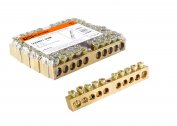
Simple screw terminals
Screw clamps for wires allow connection without breaking the cable structure. The terminal block reliably fixes wires even from different alloys, such as copper and aluminum.
The design of the device is a channel of metal (bronze, brass) of small length with a small diameter. There are two threaded holes on the channel for installing the fixing screws. Usually, single-use screws on a polyethylene basis or plastic are used in everyday life. The connection of two segments is carried out by installing the end parts in the channel from two sides, after which the screws are fixed.
Various clamp configurations can be found depending on the installation parameters. These include:
- wire diameter;
- insulation class;
- number of contact points;
- current characteristics.
Screw terminals are suitable for any technical conditions common in the domestic sector.
Self-tightening and lever clamping structures
Such mechanisms are characterized by increased usability. To work with self-tightening disposable clamps, it is enough to insert the stripped end of the wire into the hole until it stops.
The plate clamps for connecting the conductor have a spring inside, which prevents the conductor from slipping. When laying inside the cable, the plate is compressed by the core and blocks the wire. To pull out the wire if necessary, you need to squeeze the plate through the hole in the second row with a screwdriver. This type of clamping device can withstand 3-4 reconnections.
A configuration where levers are used instead of screws is considered more convenient. The wire rises with the help of a plate, which is fixed by a lever. For the operation of such a device, it is enough to raise the lever, insert the cable into the channel and lower the mechanism until it clicks. The reverse procedure is performed to pull out the wire.
Connecting insulating clamps
Spiral clamps for wires are used to connect small-diameter conductors. Several wires are stripped, formed into a group and covered with an insulating mechanism until they stop. For reliable fixation, the cap should be turned several times. The contraction of several cores is carried out by a conical spiral. When screwing the cap, the group of cables is pulled into a single unit.
Plastic cap connectors are used for low power wiring. Also, such clamps are used when installing electrical networks inside the house.
Varieties of caps:
- without persistent ledges;
- with persistent ledges.
The second type is used for wires with a large diameter.
Piercing clamping mechanism
Power lines up to 1 kW use piercing clamps. They allow you to connect segments with a cross section of 1.5-10 sq. Mm on the branch lines and with an area of 16-95 sq. Mm. on the trunk.
Structurally, they are a metal girth, which is covered with insulation. It is compressed with a stop bolt. Metal teeth are applied to the grasping plate, which pierce the insulation and bite into the conductor itself, reliably fixing it.
The advantages of puncturing an electric cable can include the possibility of abandoning the operation to remove the insulating layer. Also, when working with a clamp, a power outage on the line is not required. High-level sealing is created in relation to atmospheric influences, such as ultraviolet radiation, moisture.
SIP piercing mechanisms
Using such mechanisms, it is possible to connect a self-supporting insulated wire to a bare wire without wasting time on stripping the insulation. They are made of reinforced fiberglass and polymers.
There are two options for clamps for SIP:
- with one bolt;
- with two bolts.
The first method is also called naked SIP. Suitable for connecting bare wires to SIP.
The second method with two bolts is used in the connection on the main highways. The case is made of glass reinforced polymer.
Clamp between nut and bolt
A simple and reliable way of fixing with bolt clamping devices is actively used on power networks.
The connection will require the following details:
- a bolt of the appropriate diameter;
- nut;
- washers;
- lock-nut.
This method can even connect conductors of different materials.
Clips for other use
In addition to the mechanisms that are used to connect electrical conductors, there are models for other tasks. These include clamps for mounting suspensions, for test tasks, such as “crocodile” and others.
Anchor clamps for mounting
 This design is used for fastening cables with a cross section from 2 to 25 square mm. It can connect from two to four wires. It consists of a box with clamps for cables and wires from a housing made of a polymer material, which has a self-adjusting clamping mechanism.
This device is not used for connecting wires. It is designed specifically for installation - mounting in suspension. There are different configurations of anchor clamps for sip wires. These include:
- models for self-supporting systems;
- models for isolated neutral.
The mechanisms themselves are easy to use. For fastening there is an opening arc on which you can install brackets, hooks and other devices, which will then be mounted on the body of the clamp wires.
Clips for test tasks
There are many tasks in electronics and electrical engineering that require clamps for test use. This can be a test of the device’s performance using a tester, measurement of current or voltage level, or temporary connection to a power source. For such work, sliding or push structures with spikes called “crocodiles” are suitable. They are made of metal and coated with a PVC insulator. The gear part should be open.
Clips for test work can be divided into two large groups - for high-voltage and low-voltage electronics. Their difference lies in different boundary conditions for current and voltage.When working, it is important not to confuse the types of test clamping mechanisms, so as not to damage the device.
Correct cable connection
The correct procedure for connecting cables using clamping mechanisms ensures high-quality, safe and stable contact. To correctly connect the two cores, you need to follow the above algorithm.
Step-by-step instructions for connecting cables:
- Removal of working conductors to the contact point.
- Disconnecting the network, pulling the device out of the outlet if the wire is being built up on household appliances.
- Stripping on the clamp entry area. You can clean the ends with a knife or using a special tool. The latter option is preferable, since professional equipment will not damage thin wires. Stripping is carried out until a characteristic shine of the wire appears.
- Install uninsulated cable parts inside the clamp sleeve.
- Fastening in the appropriate way. It can be electric punctures, tightening, squeezing and other types of fixation.
If necessary, you can additionally insulate the contact point.
Typically, the work of connecting wires using different devices is carried out in junction boxes, so safety precautions must be observed.


