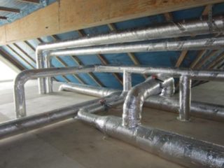
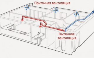
Boxes of ventilation ducts are made of round, rectangular cross-section, steel, plastic or metallized foil are used. At the design stage, the calculation of the area of air ducts and fittings is done to guarantee standard indicators of pressure and air speed, to ensure optimal acoustic characteristics.
The need and purpose of calculating the area of ducts

The layout of the ventilation ducts is an important part of the air distribution system. The calculation of the cross-section of the duct plays a role in determining the required flow of material in order to save money. The microclimate in the room depends on the correct calculation of the working area and configuration.
An error-free calculation of the throughput and pipe diameter affects the characteristics of:
- air purity;
- air exchange rates;
- risk of mold and mildew;
- temperature in the room.
As a result of calculating the ventilation indices, a design should be obtained that allows the necessary amount of fresh flows to pass through to improve the internal atmosphere. At the same time, pressure losses in the mains are minimized, and the microclimate complies with sanitary standards for humidity, air pollution and noise level from air ducts.
General Information for Computing

Key indicators include the cross-sectional area of the box, which determines the speed of movement of flows. The pattern is manifested in the fact that with an increase in size, the pressure decreases and vice versa. Calculation of the quadrature of the ducts is carried out in several ways in order to be able to compare the results.
The indicators for choosing pipes can be calculated by the values:
- in accordance with hygiene and sanitary standards given in SanPiN;
- by the number of people in the room;
- by area and volume of the room.
Counting is carried out for a separate room or building as a whole. The amount of material is determined based on the configuration and dimensions of the system. For round pipes, diameter and total length are needed, and rectangular pipes are calculated using the width, height and length of the trunk.
The surface area of the molded parts of the ducts is determined taking into account bends, adapters of various shapes, their width, rotation angle and height are taken into account.
Methods and steps for calculating the area of ducts
The size of the ventilation duct depends on the volume of the pumped flow, the speed of movement and the pressure on the internal walls.
The calculation of the parameters of the ventilation line is carried out in several stages:
- the rate of air exchange is determined in accordance with technical requirements, construction and sanitary standards;
- aerodynamic selection of the pipeline section is done;
- the level of generated noise is determined (acoustic calculation);
- a laying scheme with reference to the layout is drawn on paper;
- the drawing is agreed with the customer, changes are made;
- Settlement documents for power supply are drawn up;
- individual nodes of the air duct with detailing are drawn.
Ventilation equipment is selected only after technical calculation of air ducts and fittings; air heaters, supply and exhaust units, and automatic devices are purchased.
Section calculation
Noise effects are reduced with the expansion of the channels, but in practice the increase in cross section is not always justified. This may be hindered by the limited size of the room in height, so attention is paid to the calculation of the perimeter.
The calculation of the transverse area of the ducts is made according to the formula Sc = L2.788 / Vwhere:
- Sc - estimated box area (cm2);
- L - the volume of flow passing through the channel per hour (m3 / h);
- V - air velocity in the highway (m / s);
- 2,788 - conversion rate of units.
The area is obtained in square centimeters, such units are most convenient for analysis. The flow velocity in the channel is taken at the level of 3 - 4 m / s for residential premises. It is possible to reduce the diameter of a round pipe by replacing it with a rectangular one, which has a similar area across.
Calculation of square meters of air ducts is done for each section separately, starting from the central channel, where the speed reaches 6 - 8 m / s. The diameter of the main duct is often larger than the diameter of the bends, while the channels are connected by adapters.
Calculation of the perimeter of the rectangle and the area of the circle
The area of the ventilation ducts is taken after calculating the required performance. The cross section of the pipes refers to the design characteristics, which determine the optimal configuration of the duct (rectangular or round). The length of the line is made as small as possible to save materials, but the system should provide the required multiplicity of exchange.
The circular cross-sectional area is calculated by the formula S = πD2 / 400and rectangular - S = a b / 100where:
- S - area;
- π - the number 3.14;
- D - circle diameter;
- a - the length of the rectangle;
- b - the width of the rectangle.
The ratio of the area with the diameter, length and width is reduced for convenience in a special SNiP table where you can analyze and find out the parameters depending on the size of the section. In everyday life, the most common are boxes with a cross section of 40 x 20 or 10 x 10 cm, round channels with a diameter of 20 and 10 cm are used.
Air speed calculation
 The flow rate in ventilation is determined after calculating the rate of air exchange, which can be calculated independently or see in the tables. The multiplicity shows the intensity of the air change. The indicator is determined by the number of atmospheric exchanges per hour and is equal to the ratio of cubic flow to the volume of the room where ventilation is installed.
The rate of air exchange is found by the formula N = V / Wwhere:
- N - number of air replacements (times / h);
- V - cubic meter of fresh air per hour (m3 / h);
- W - volume of the room (m3).
After that, the actual flow velocity (aerodynamic calculation) in the channel is calculated by the formula £ = L / 3600Fwhere:
- £ - flow rate (m / s);
- L - air exchange rate (m3 / h);
- F - pipe cross-sectional area (m2).
The speed affects the noise level, so when choosing the parameters of the pipeline, you should compare this characteristic with that taken from the normative tables.
Shaped products and their calculation
The size of the curly elements in the trunk is determined using the online calculator or using special tables in collections. Products differ in complex shape, for the calculation you need to have special knowledge.
Shaped links include elements:
- round, oval, square and rectangular bends are placed to rotate the pipeline at an angle;
- transitions are used for joining boxes of different sections, differ in complex section geometry;
- nipples and couplings connect straight sections of the duct;
- tees are used for branching the channel;
- plugs interrupt the flow;
- crosses are used to separate or combine adjacent streams;
- ducks are put to translate the axis of the pipeline to another position vertically or horizontally.
The speed of air, its volume, the tightness of the system and the cost of electricity depend on the parameters of the fittings.
Actual duct area
In addition to the calculated one, it is necessary to calculate the actual area of the already installed channel. For each section, there are special calculation formulas. The dimensions of the diameter, width and length are not taken by the method of selection from regulatory documents, for the correct determination you need to measure the distance, perimeter and length in place. Formulas for calculating the actual cross-sectional area of a rectangular shape are used similarly to those used for the calculated indicator. For the area of the round duct, also measure the diameter.
The oval cross-sectional area is calculated by the formula S = π · A · B / 400where:
- π - the number 3.14;
- A - diameter along the major axis of the oval;
- B - diameter along the smaller axis of the oval.
Actual duct performance is compared with regulatory performance and compliance is determined.
Methods for calculating shaped products
An error in the choice of cross-sections of the figured parts can lead to improper air flow circulation even with an error-free design. Many manufacturers give nomograms in the explanatory note to the project. These are graphical calculations of the function for several variables presented in the normative literature.
Engineering assistance in calculating ducts says that there is a way of applying a ruler, with which functional dependencies are worked out without using formulas. From the monograms, the cross-sectional area of the fittings of the duct is taken, which is able to balance the noise level in the system.
The following steps are taken to determine the pipe dimensions for branching or turning:
- find on the monogram the point of intersection of the air flow moving in an hour and the line of optimal speed for a given section;
- close to this point find the value of a suitable diameter.
Using the nomogram, the calculation of the area of the shaped parts of the ducts is facilitated, the decrease in pressure in the system at a specified flow rate is specified.
Basic calculation requirements
The location of the ventilation pipeline is determined at the stage of designing the project, while preparing the sites for the installation of engineering equipment, laying the number of bends, transitions, tees and crosses.
The design of the ducts must guarantee the conditions:
- the building provides the required temperature with heat transfer to the required premises;
- the air velocity in the channels does not reduce the level of human comfort;
- harmful chemical particles and suspended impurities are present in the atmosphere in an amount that is allowed by sanitary standards.
In some areas, constant pressure should be maintained and outside air should not be allowed. For proper functioning, the resistance of the inner surface of the duct is analyzed.
Determination of pressure loss after calculating the duct area
Pressure losses are calculated after calculating the area of pipelines, air exchange rate and resistance of engineering communications. This indicator affects the selection of fan power.
Formula used P = R · L + E · V · Y / 2where:
- P - pressure loss (Pa);
- R - specific indicator of friction pressure during the interaction of air with internal walls (Pa / m);
- L - the length of the settlement section (m);
- E - the numerical index of pressure losses in the area in the total;
- V - flow rate in the desired location (m / s);
- Y - atmospheric density (kg / m3).
Pressure loss is determined using the manual. The coefficient E is directly dependent on the parameters of the plot where the calculation is done.
Using an automatic online calculator improves the accuracy of the calculation compared to the manual method.


